

Detector Placement: Where Should Fixed Gas Sensors Be Installed?
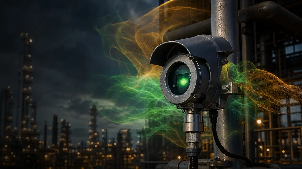
Most conversations about fixed gas detection revolve around the instrument: which sensor, which brand, which certification. But once the transmitter is mounted, none of that matters if the gas never reaches it. Placement is where engineering meets the atmosphere - and it is the step most frequently skipped, delegated to whoever holds the bracket inventory.
Done well, placement is a quantitative exercise with software, standards, and measurable coverage targets. Here is the discipline, from first principles to the tools that automate it.
01Let Gas Density Choose the Height
Gases stratify by vapor density relative to air. Sensors must wait for the gas at the elevation where the gas will actually arrive.
- Lighter than air (methane, hydrogen, ammonia): mount high - above leak sources, near rooflines, under canopies where pockets can accumulate
- Similar to air (carbon monoxide, nitrogen): mid-level, close to the source and breathing zone
- Heavier than air (H2S, LPG, chlorine, butane): low - near grade, in pits and trenches where heavy vapors pool, but above likely liquid accumulation points
The Stratification Rule
Sensor elevation follows vapor density - one plant, three heights.
02Start at the Leak Sources, Not the Walkways
Every valve, flange, seal, drain, and sample point is a candidate release. Detectors belong close to where gas can first escape - pumps, compressors, and fittings - with coverage built outward. Walkways and perimeters come second, as boundary monitoring, not the primary detection layer.
03Respect the Wind and the Ventilation
Air movement decides where a plume travels - and where it never arrives. Prevailing wind shifts outdoor plumes; HVAC and natural ventilation dominate indoors. A sensor downstream of the wind on the day of the leak is the one that matters.
- Use prevailing wind roses for outdoor layouts - but remember wind direction is seasonal, so coverage must work for all quadrants
- Keep detectors out of fresh-air inlets, discharge streams, and direct washdown or steam paths that dilute or flood the sample
- In enclosed spaces, place detectors where ventilation patterns carry escaping gas - and consider aspirated sampling where diffusion is too slow
04Point, Open-Path, or Ultrasonic - Match the Geometry
Not every location wants a point sensor. Long fences and perimeters favor open-path IR; outdoor turbine enclosures and vast process areas increasingly use ultrasonic leak detection that hears a release regardless of wind or dilution. Congested modules with complex geometry favor dense point coverage. The geometry of the space chooses the technology as often as the gas does.
05Don't Forget Access, Obstruction, and Maintainability
A detector behind a cable tray, inside a structural pocket, or reachable only by scaffold will drift quietly out of service. Placement must account for physical obstruction of gas flow, clearance for calibration gas access, and the realistic maintenance burden of every location you choose.
Historically, placement was a rulebook exercise: spacing tables, "one detector per X square meters," and engineering judgment. Modern practice is performance-based, anchored on ISA-TR84.00.07 - the technical report that defines how to evaluate fire and gas system effectiveness using geographic coverage (what fraction of the monitored volume can actually be detected) and scenario coverage (what fraction of credible releases will be caught) instead of rule-of-thumb spacing.
That shift turned detector placement into a modeling problem - and a family of software tools now exists for it:
Software for Detector Placement & Dispersion
The tools used on real projects, grouped by role in the workflow.
| Tool | What It Does | Role in Placement |
|---|---|---|
| Detect3D | Purpose-built 3D fire & gas mapping - imports your CAD plant model, models detector types, and computes coverage | The placement optimizer: finds the best detector positions and validates coverage against ISA-TR84.00.07 targets |
| Gexcon FLACS | CFD simulation of gas dispersion and explosions in congested geometry | Predicts realistic gas cloud shapes and behavior for complex sites - feeds placement studies |
| DNV Phast | Consequence modeling of releases - dispersion, fire, explosion footprints | Defines the credible release scenarios and hazard zones that detectors must cover |
| DNV Safeti | Quantitative risk assessment - combines consequence and likelihood | Risk-ranked placement: puts detectors where risk, not just geometry, demands them |
| ANSYS Fluent | General-purpose CFD including ventilation and dispersion studies | Indoor airflow and enclosure studies where standard correlations fail |
| NIST FDS | Open-source computational fire and dispersion model | No-cost option for smoke and gas movement studies |
| EPA ALOHA | Free screening-level atmospheric dispersion model | Quick answers for simpler sites and initial screening |
How the Tools Fit Together
Define scenarios. Identify leak sources and use Phast or FLACS to model how credible releases disperse under site wind and geometry.
Map the plant. Import the 3D model into Detect3D, place candidate detectors, and compute geographic and scenario coverage.
Optimize. Let the tool iterate - fewer detectors at better positions, or added units where coverage falls short of target.
Document. Export coverage reports for the safety case, HAZOP actions, and future modification audits - placement becomes a living record, not tribal knowledge.
The Multiplier Effect
Every rupee spent on a better sensor is multiplied - or nullified - by placement. Software-assisted placement routinely finds that existing layouts have blind zones no spacing table would have revealed, and that modest repositioning achieves coverage targets with fewer detectors than the original grid. Placement is the cheapest performance upgrade available in fixed gas detection.
Placement Review Checklist
- Every sensor's height justified by the target gas's vapor density
- Leak sources mapped - valves, seals, pumps, drains - before walkways and fences
- Detectors clear of ventilation discharges, steam plumes, and washdown spray
- Wind rose reviewed for outdoor areas; ventilation flows reviewed for indoor ones
- Technology matched to geometry: point, open-path, or ultrasonic
- Physical obstruction and calibration access verified for every position
- Coverage validated with mapping software against ISA-TR84.00.07 targets - and re-validated after plant changes
Placement decisions deserve the same engineering rigor as the detectors themselves. If you are planning a new installation or auditing an existing one, explore our range of fixed and portable gas detection solutions, or reach us through respoproducts.com for application support before your layout is frozen.
Volume 30 of 53 · FY26-27 · You are receiving this because you subscribed to our safety briefings.
respoproducts.com
Author: Mr. Vishal Kaushal
Volume: Volume 30 of 53 FY26-27